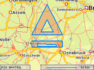
PTV xMap Server allows custom vector objects to be drawn on your maps by adding the so called GeometryLayer. In this tutorial we show you how to use a GeometryLayer and how to define vector shapes.

WKT is a textual markup language that allows you to specify vector objects on a map. The most important WKT object types are points ( POINT ), lines ( LINESTRING ) and polygons ( POLYGON ). Below you find a short introduction into the WKT format.
A point is declared with the keyword POINT followed by its X- and Y- coordinates which are separated by a space and surrounded by parenthesis. Please notice following example:
POINT(800000.0 6900000.0)
A line is declared with the keyword LINESTRING followed by a list of comma separated points. Please notice following example:
LINESTRING(800000 6860000, 800000 6880000, 900000 6880000, 900000 6860000)
A polygon is defined by a list of so called LinearRings, which are lists of points where the first and the last point are the same. If you define a polygon with only one LinearRing, you get a simple polygon with the LinearRing's points as verticals. However, if you create a polygon with more than one LinearRing, then the additional LinearRing(s) can be used to define holes within the original polygon (provided the second polygon lies within the first one).
Simple Polygon in shape of a triangle:
POLYGON( (800000 6900000, 900000 6900000, 850000 7000000, 800000 6900000) )
Polygon in shape of a triangle but with one hole:
POLYGON( (800000 6900000, 900000 6900000, 850000 7000000, 800000 6900000),
(830000 6910000, 870000 6910000, 850000 6950000, 830000 6910000) )
Click here for additional information on WKT.
Define at first both polygons. As second step create two objects as type of Geometry setting the polygons with further relevant properties.
Step 1:
Polygon polygon1 = new Polygon();
polygon1.setWkt("POLYGON((800000 6860000, 800000 6880000, 900000 6880000, 900000 6860000,
800000 6860000)" + ",(820000 6862000, 820000 6868000, 880000 6868000,
880000 6862000, 820000 6862000))");

Polygon polygon2 = new Polygon();
polygon2.setWkt("POLYGON((800000 6900000, 900000 6900000, 850000 7000000, 800000 6900000)" +
",(830000 6910000, 870000 6910000, 850000 6950000, 830000 6910000))");
Step 2:
Geometry geometry1 = new Geometry();
geometry1.setDescription("firstPolygon");
geometry1.setId(0);
geometry1.setGeometry(polygon1);
geometry1.setReferencePoint(point);

Geometry geometry2 = new Geometry();
geometry2.setDescription("secondPolygon");
geometry2.setId(1);
geometry2.setGeometry(polygon2);
geometry2.setReferencePoint(point);
);
GeometryOptions allow you to alter the appearance of the drawn shapes. You can define such properties as line color, fill color and transparency. For a complete list of options see the list below or read the PTV xMap Server API on this topic.
GeometryOptions are always applied to a group of Geometry objects called Geometries. If you have multiple Geometry objects and want to apply different styles you have to group them into different Geometries.
| BORDERCOLOR | The border color. All border values are used for the border of areas and for lines. |
| BORDERWIDTH | The width of the border in pixels. |
| BORDERALPHA | alpha blending value ( from 0 opaque to 255 completely transparent). |
| FILLCOLOR | The fill color |
| FILLALPHA | alpha blending value ( from 0 opaque to 255 completely transparent) |
| DRAWARROWS | If 1, arrows are drawn upon the line in order to mark the line's direction. |
| LINESCALEFACTOR | The scaling factor for lines which are scaled with the zoom level. 0 (default) means no scaling, 100 means linear scaling. 20 has proved to be a good value for displaying routes together with a value of 20 for the width. Please note, that this value is valid for all objects of this layer. If it occurs more than once with different values, an arbitrary value will be chosen. Please use more than one instance of GeometryLayer in that case. |
| AUTOCENTEROBJECTS | If 1, all objects of this GeometryLayer element are centered on the map. |
All colors are 24-bit RGB values. If you have 8-bit red, green and blue values, the color value equals as follows:blue*216 + green*28 + red
Step 1: Define a new method with RGB values.
// helper method to calculate the color
private static String rgbToColorString(int red, int green, int blue) {
int color = (blue<<16)+(green<<8)+(red);
return ""+color;
}
Step 2: Create geometryOptions and set some properties:
// set some geometry options to alter the appearance of the shapes
GeometryOption[] geometryOptions = new GeometryOption[]{
new GeometryOption(GeometryOptions.BORDERCOLOR, rgbToColorString(0,128,255)),
new GeometryOption(GeometryOptions.FILLCOLOR, rgbToColorString(255,0,0)),
new GeometryOption(GeometryOptions.FILLALPHA, "200"), // 0-255
new GeometryOption(GeometryOptions.AUTOCENTEROBJECTS, "1") // 0-255
};
Step 3: At least put both objects into the new instantiated array derived from the class Geometries[ ].
// bundle geometries with geometry options
Geometries geometries = new Geometries(new Geometry[]{ geometry1, geometry2},
geometryOptions);
Finally, the class GeometryLayer is defined including relevant properties in order to display the shape of the given object. Due to the opportunity to define several layers such as CustomerLayer or GeometryLayer an individual name and a corresponding draw priority should be defined.
The range of the draw priority is from 0 (minimum priority => drawn underneath all other layers) to 50000 (maximum priority => drawn above all other layers). The detailed information is added to the PTV xMap API documentation.
Also the object information is available such as the real or pixel coordinates. Set the objectInfos property whether it is needed for further actions. If ObjectInfoType.GEOMETRY is added the coordinates of each point from the above defined shape will be output in the result list. Further properties and their meaning are also documented in the PTV xMap API documentation.
Add layer as a new GeometryLayer object and set name, geometries, draw priorities, visibility and object information.
public static final int PRIORSTREET=150;

// put the geometries into a layer
GeometryLayer layer = new GeometryLayer();
layer.setName("geomLayer");
layer.setDrawPriority(DrawPriorities.PRIORSTREET);
layer.setVisible(true);
layer.setGeometries(new Geometries[]{geometries});
layer.setObjectInfos(ObjectInfoType.GEOMETRY);
The example mapping with GeometryLayer is also executable as a stand-alone java program.
Copyright © 2025 PTV Logistics GmbH All rights reserved. | Imprint